News

Exner Turbidity and Solids Sensors Receive 3A and EHEDG Hygienic Certifications
Industrial sensors now meet stringent sanitary design standards for brewing, dairy, and pharmaceutical applications Auburn, Calif. – South Fork Instruments announces that Exner turbidity and solids concentration sensors have received both 3A Sanitary Standards and […]

Manufacturers Aim to Speed Product Delivery Amid Supply Chain Issues
The global supply chain is in crisis because of the COVID pandemic. The world is facing supply shortages caused by reduced labor availability and increased (albeit, necessarily increased) regulatory actions. Issues persisted throughout 2021 and […]

How Hycontrol Overcame Challenges with Industrial Foam Detection
We all experience foam every day. Foam forms when squeezing a bath sponge, shaking a can of soda, or whipping a cup of coffee. Foam also arises in many industrial processes. It can be produced […]
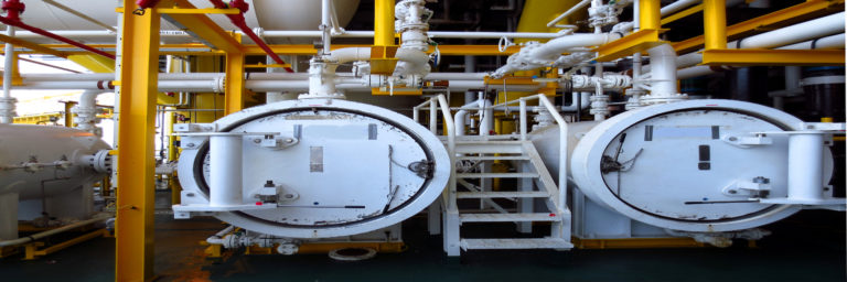
Do Bubbles Matter When Measuring With Coriolis Meters?
I’m often asked whether Coriolis meters can measure mixed gas/liquid streams accurately. Unfortunately, the answer is not a simple yes or no. This is due to the volume of published material that offers information regarding […]
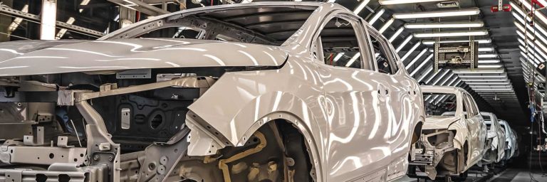
Compact Coriolis Flow Meters for Paint & Adhesive Coating Metering
Machines for mixing and delivering two-part (or more) chemicals for paint and adhesive coatings in industrial manufacturing plants must be accurate and reliable if the quality of the final product is to be maintained. High […]

How Automatic Retractors Can Improve pH/ORP Sensor Measurements in Your Process
One of the most labor intensive maintenance efforts in a plant relates to the figurative care and feeding of pH and ORP probes and other electrochemical sensors. While many such probes are touted as “rugged,” […]
SOUTH FORK INSTRUMENTS
3845 Buffalo Road
Auburn, CA 95602
Tel: (+1) 925-461-5059